 English
 Deutsch
 Tiếng Việt
AutoCAD Point Cloud Masterclass: 3D Snapping, Dynamic UCS, Section Planes & Cropping States
A deep-dive technical masterclass on extracting 2D geometries from 3D point clouds in AutoCAD: 3D Object Snaps (3DOSNAP), Dynamic UCS, Section Planes, and Cropping States by Lynn Allen.
Original concepts & technical insights by Lynn Allen (Autodesk AutoCAD Evangelist).
Source Publication: Autodesk Official AutoCAD Blog — Lynn Allen Tuesday Tips.
Adapted with German DIN 1356 architectural standards by 1000Ants Studio.
When working with dense 3D laser scan datasets inside AutoCAD, standard 2D drafting methods are not enough. Drafting over millions of spatial points requires specialized tools for snapping, coordinate alignment, section slicing, and viewport clipping. In this in-depth guide, inspired by Lynn Allen's renowned AutoCAD Tuesday Tips series, we explore the definitive toolset for mastering point clouds in production environments.
1. Specialized 3D Object Snaps (3DOSNAP) for Point Clouds
Standard 2D object snaps (OSNAP) often jump erratically across point clouds because they cannot distinguish between foreground walls and background clutter. AutoCAD solves this with dedicated 3D Object Snaps (3DOSNAP) specifically engineered for laser scan point clouds:
| 3D Snap Mode | Geometric Calculation | Drafting Application |
|---|---|---|
| Node / Point | Snaps to the single closest scanned point in 3D space. | Checking raw spot elevations and benchmark coordinates. |
| Intersection | Calculates the virtual line where two segmented planar surfaces intersect. | Snapping precisely to wall-to-wall or wall-to-ceiling corners. |
| Edge & Corner | Identifies sharp boundary transitions between adjacent planes. | Tracing columns, concrete beams, door openings, and window sills. |
| Perpendicular to Edge | Projects a true 90° normal onto the nearest planar segment. | Dimensioning wall thicknesses and structural offsets. |
| Centerline | Computes the cylindrical center axis of pipes, conduits, and round columns. | Industrial MEP drafting, plant piping routing, column grid layouts. |
Figure 1: 3D Object Snap modes and point cloud visual parameters. (Image Source: Autodesk AutoCAD)
2. Dynamic UCS (F6) on Point Cloud Planes
In older CAD workflows, drawing on slanted roofs or non-orthogonal historical walls required creating custom named User Coordinate Systems (UCS) with multiple clicks. With Dynamic UCS enabled (press F6 or toggle in the Status Bar):
- Start any drawing command (e.g.,
PLINE,RECTANG, orCIRCLE). - Hover your crosshair over any planar surface in the point cloud.
- AutoCAD automatically detects the surface normal and aligns the XY drawing plane to that face in real-time.
- Click and draw directly on the face with perfect planarity!
3. Section Planes & Extracting 2D Linework
To produce 2D floor plans from a dense building scan:
- On the Point Cloud contextual ribbon, click the Section Plane drop-down menu.
- Select Live Section and position the cutting plane at +1.00m above the floor level.
- Use Extract Section Lines to allow AutoCAD to automatically analyze the sliced points and generate clean 2D polyline perimeter outlines.
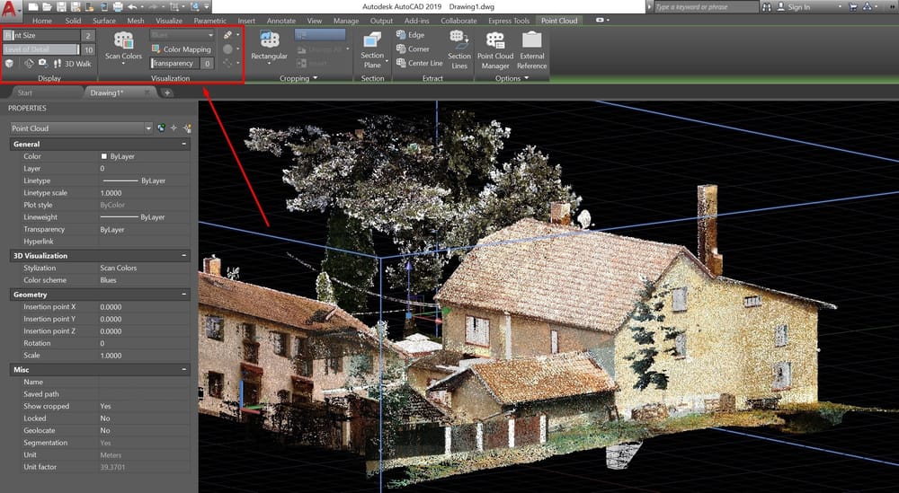
Figure 2: Color ramp elevation slicing for accurate floor elevation tracing. (Image Source: Autodesk AutoCAD)
4. Cropping Panel & Named Cropping States
Displaying an entire 20-story building simultaneously overwhelms system RAM. Use the Cropping panel to create rectangular, polygonal, or circular boundaries. Save these setups as Named Cropping States (e.g., "Ground Floor North Wing", "Level 2 Mezzanine", "Roof HVAC") to switch between viewports in 1 second.
Need High-Precision Scan-to-CAD Drafting?
At 1000Ants Studio, our team of dedicated CAD drafters transforms raw point clouds into fully layered, millimeter-accurate 2D CAD drawings and 3D Revit models adhering strictly to German DIN 1356 standards. Contact us today for a free project quote →
Article Reference: Autodesk AutoCAD Blog / Lynn Allen Tuesday Tips Series.