
 English
 Deutsch
 Tiếng Việt
Mastering Point Clouds in AutoCAD: The Complete Step-by-Step Technical Guide
A complete masterclass on processing 3D laser scans in Autodesk ReCap (.rcp/.rcs), inserting clouds, fixing XRef links, configuring RGB/Intensity/Elevation stylization, and aligning survey coordinate systems.
Original workflow concepts based on Autodesk AutoCAD & ReCap Point Cloud Architecture and field practices by LaVa Scan & Lynn Allen.
Original Source: Autodesk Official AutoCAD Blog & LaVa Scan Blog.
Curated and expanded with German DIN 1356 standards by 1000Ants Studio.
Working with 3D laser scan data (Point Clouds) in AutoCAD has revolutionized how architects, structural engineers, and BIM specialists document existing buildings. Whether you are drafting historical renovation plans, industrial facility layouts, or precise MEP coordination models, point clouds eliminate measuring errors by capturing millions of real-world coordinate points (X, Y, Z).
However, handling massive point cloud datasets (often exceeding 10–50 GB) inside AutoCAD requires the correct pipeline. In this comprehensive guide, our technical team at 1000Ants Studio walks you through every stage: file indexing, canvas insertion, missing path resolution, display optimization, 3D object snapping, and georeferencing.
1. Preparing Laser Scan Data with Autodesk ReCap (.RCP / .RCS)
AutoCAD cannot natively read raw laser scanning formats (such as .e57, .pts, .las, .xyz, or .fls) because they lack spatial indexing. To ensure buttery-smooth navigation, Autodesk uses its proprietary ReCap indexing engine.
- Autodesk ReCap: A lightweight software (available for free download from Autodesk) that imports raw scans, filters noise, aligns stations, and compiles them into an .rcp (project file) accompanied by .rcs (individual scan files) inside a
Support/directory. - Hardware Requirements: We recommend AutoCAD 2018 or newer running on a dedicated 64-bit multi-core CPU with at least 16–32 GB of RAM and hardware acceleration enabled (
GRAPHICSCONFIG).
Figure 1: Indexing raw scan formats into .RCP projects inside Autodesk ReCap. (Image Source: Autodesk / LaVa Scan)
2. Inserting a Point Cloud into a New AutoCAD Drawing
Once your scan is indexed in ReCap, ensure that the .rcp file and its matching Support folder remain in the exact same directory. There are two primary insertion methods:
Method 1: Direct Drag & Drop
- Open AutoCAD and create a new drawing using your standard architectural template (
.dwt). - Open Windows File Explorer (or macOS Finder), select your
.rcpfile, and drag it directly into the AutoCAD model space drawing area. - AutoCAD prompts you for insertion parameters in the command line:
- Specify insertion point: Press
Enterto accept default(0, 0, 0)coordinates. - Scale factor: Type
1(or pressEnter). - Rotation angle: Type
0(or pressEnter).
- Specify insertion point: Press
- Double-click the mouse scroll wheel (or run
ZOOM➔Extents) to center the point cloud on screen.
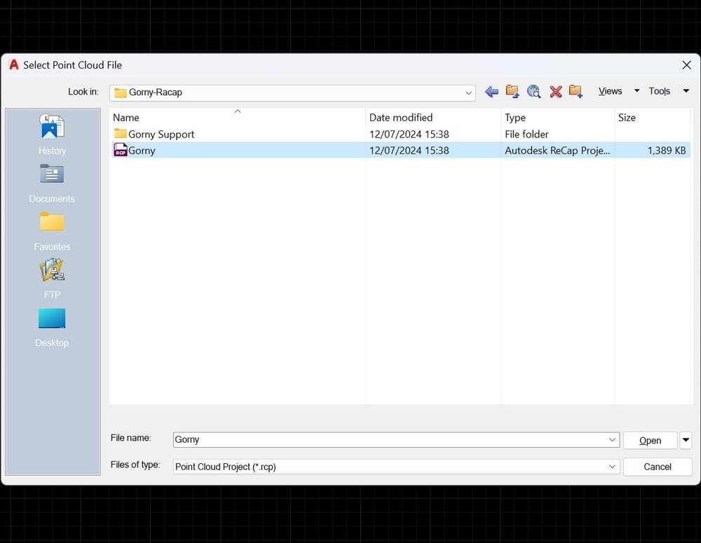
Figure 2: Dragging the .rcp file directly onto the model space canvas. (Image Source: Autodesk / LaVa Scan)
Method 2: Point Cloud Attach via Ribbon
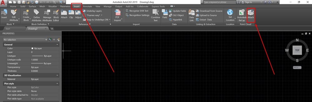
- Navigate to the Insert tab on the AutoCAD top ribbon.
- In the Point Cloud panel, click the Attach button (or type
POINTCLOUDATTACH). - Browse to your
.rcpfile and click Open. - In the Attach Point Cloud dialog box, ensure the checkboxes for Insertion Point, Scale, and Rotation are **UNCHECKED** (Specify On-Screen = Off). This guarantees the point cloud is inserted at its authentic real-world origin with a true 1:1 metric scale.
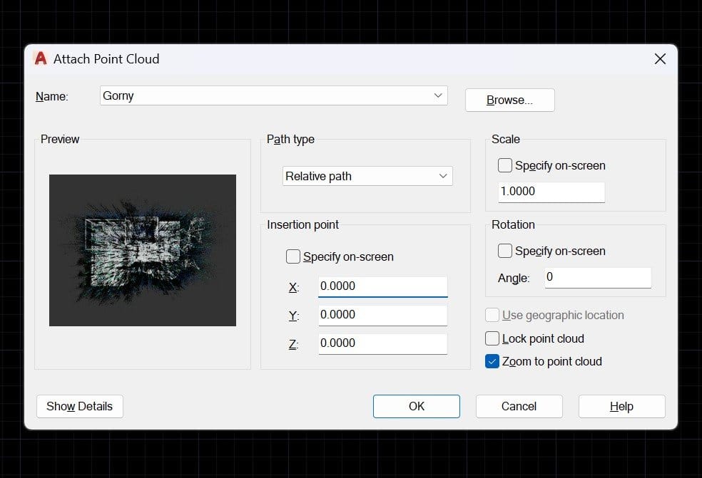
Figure 3: Attaching a point cloud through the Insert ribbon panel. (Image Source: Autodesk / LaVa Scan)
3. Managing External References (XRefs) & Fixing Missing Paths
Due to the massive file sizes involved, AutoCAD never embeds point cloud data directly inside the .dwg drawing file. Instead, it links to the cloud externally via the External Reference (XREF) system. If you move your project folders, share archives with clients, or transfer data over Google Drive/Dropbox, AutoCAD will display an empty bounding box with an unresolved path label.
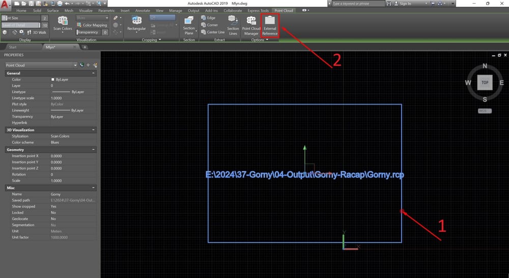
Figure 4: The 6-step workflow for relinking unresolved point cloud paths in the XREF manager. (Image Source: Autodesk / LaVa Scan)
Step-by-Step Path Repair Protocol:
- Extract all downloaded project archives into a permanent local directory. Confirm that the
.rcpfile and theSupportfolder are siblings in the same folder. - Open the
.dwgdrawing in AutoCAD and select the empty bounding box (Step #1). - On the contextual ribbon tab, click External References (or type
XREF) (Step #2). - In the XRef Manager palette, find the row with the cloud icon and select it (Step #3).
- In the details panel below, locate the Saved Path field (Step #4).
- Click the browse button (
...), navigate to the location of the.rcpfile on your local machine, and click Open (Steps #5 & #6). - The point cloud will immediately reload on your screen at its exact surveyed position.
4. Display & Visual Stylization Settings in AutoCAD
Clicking directly on any inserted point cloud reveals the Point Cloud Contextual Tab on the AutoCAD ribbon. Here you can customize point density, point size, transparency, and color stylizations to maximize drafting readability:
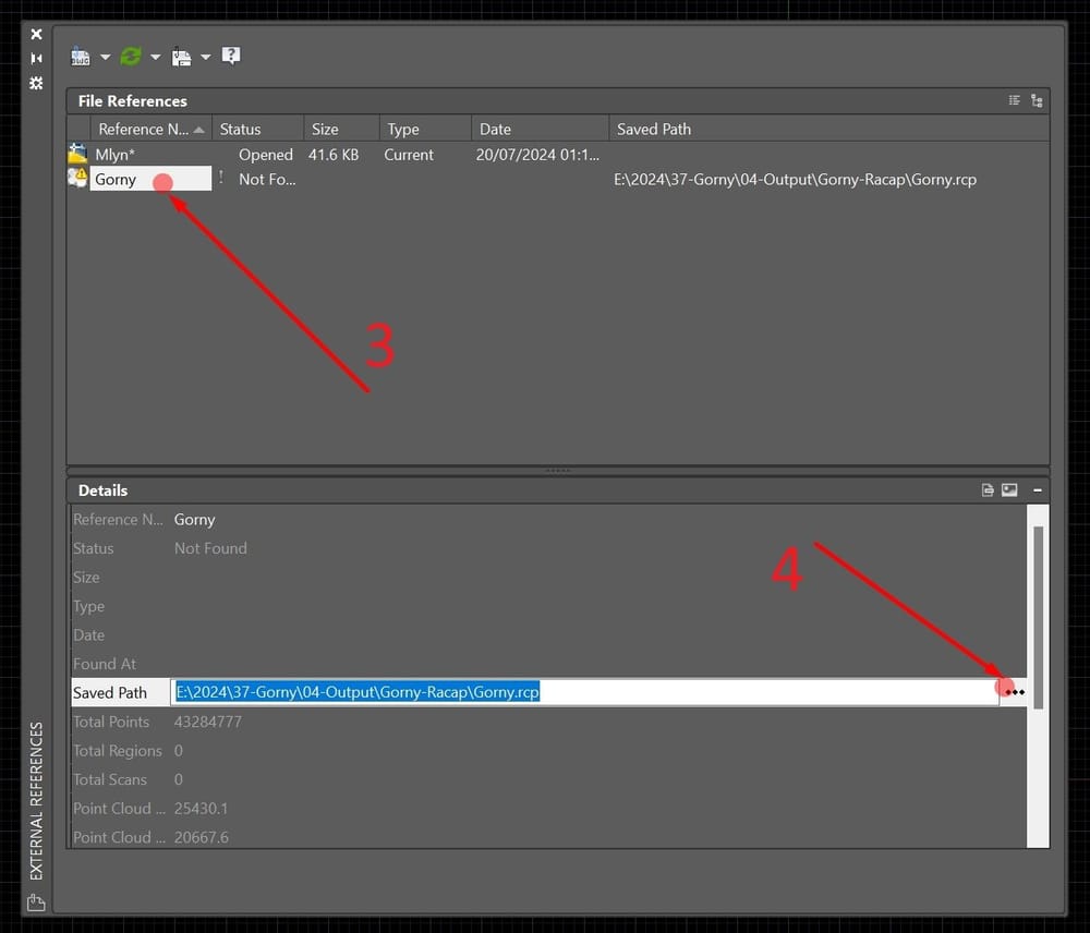
Figure 5: Stylization modes and visualization controls. (Image Source: Autodesk / LaVa Scan)
| Stylization Mode | Technical Description | Best Used For |
|---|---|---|
| Scan Color (RGB) | Renders real photographic true colors captured by the scanner's HDR camera. | Visual inspections, client presentations, material identification. |
| Object Color | Overrides all points with a single uniform color chosen by the user. | High-contrast drafting against dark backgrounds; tracing linework. |
| Intensity | Renders surfaces based on laser beam reflectivity values (greyscale or false-color). | Tracing sharp wall edges, mortar joints, pavement stripes, metallic columns. |
| Normals | Colors points based on the 3D angular direction (normal vector) of the surface. | Distinguishing vertical walls from horizontal floors and slanted roofs. |
| Elevation (Color Ramp) | Applies an adaptive spectrum color ramp according to Z-axis elevation values. | Topographical surveys, floor level checks, multi-story building drafting. |
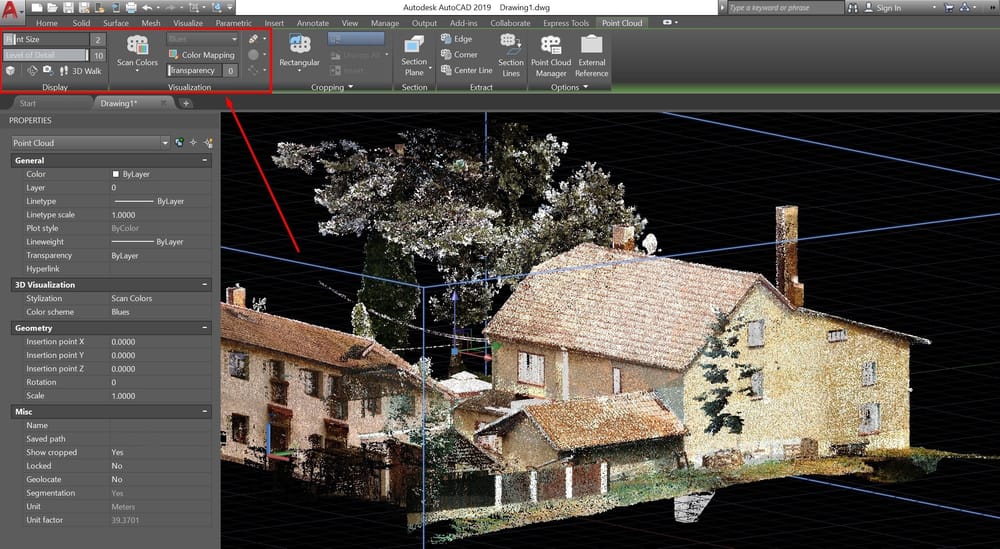
Figure 6: Elevation color ramp highlighting structural height layers. (Image Source: Autodesk / LaVa Scan)
5. Georeferencing & Survey Coordinate Transformation
In field scanning, every individual scanner setup has its own local origin (0, 0, 0) located at the optical center of the instrument. When surveying large complexes, multiple scan stations are registered (stitched) together in software such as Leica Cyclone, FARO SCENE, or Trimble RealWorks.
To convert arbitrary scan coordinates into official state plane or local project grid coordinates:
- Surveyors place checkerboard targets or retroreflective spheres at known geodetic benchmarks.
- Total stations measure the precise millimeter coordinates of these targets.
- During registration, the scan software automatically correlates the scanned targets with the measured coordinates, translating and rotating the entire point cloud into the official coordinate system.
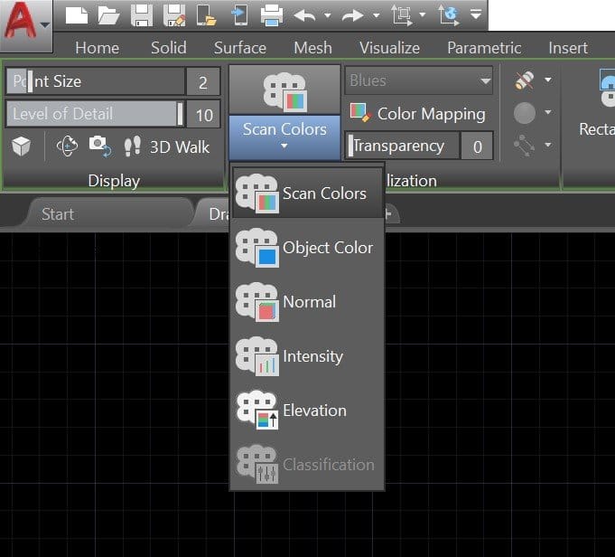
Figure 7: Survey target markers used to transform scan coordinates. (Image Source: Autodesk / LaVa Scan)
Outsource Your Point Cloud to CAD Drafting with 1000Ants Studio
Drafting precise 2D architectural plans (floor plans, sections, elevations) and 3D Revit models from point clouds requires specialized expertise and significant drafting hours. At 1000Ants Studio, our senior CAD engineers maintain strict compliance with German DIN 1356 standards, delivering millimeter-accurate drawings with clear layer structures and lightning-fast turnaround times.
Request a Free Project Quote →